
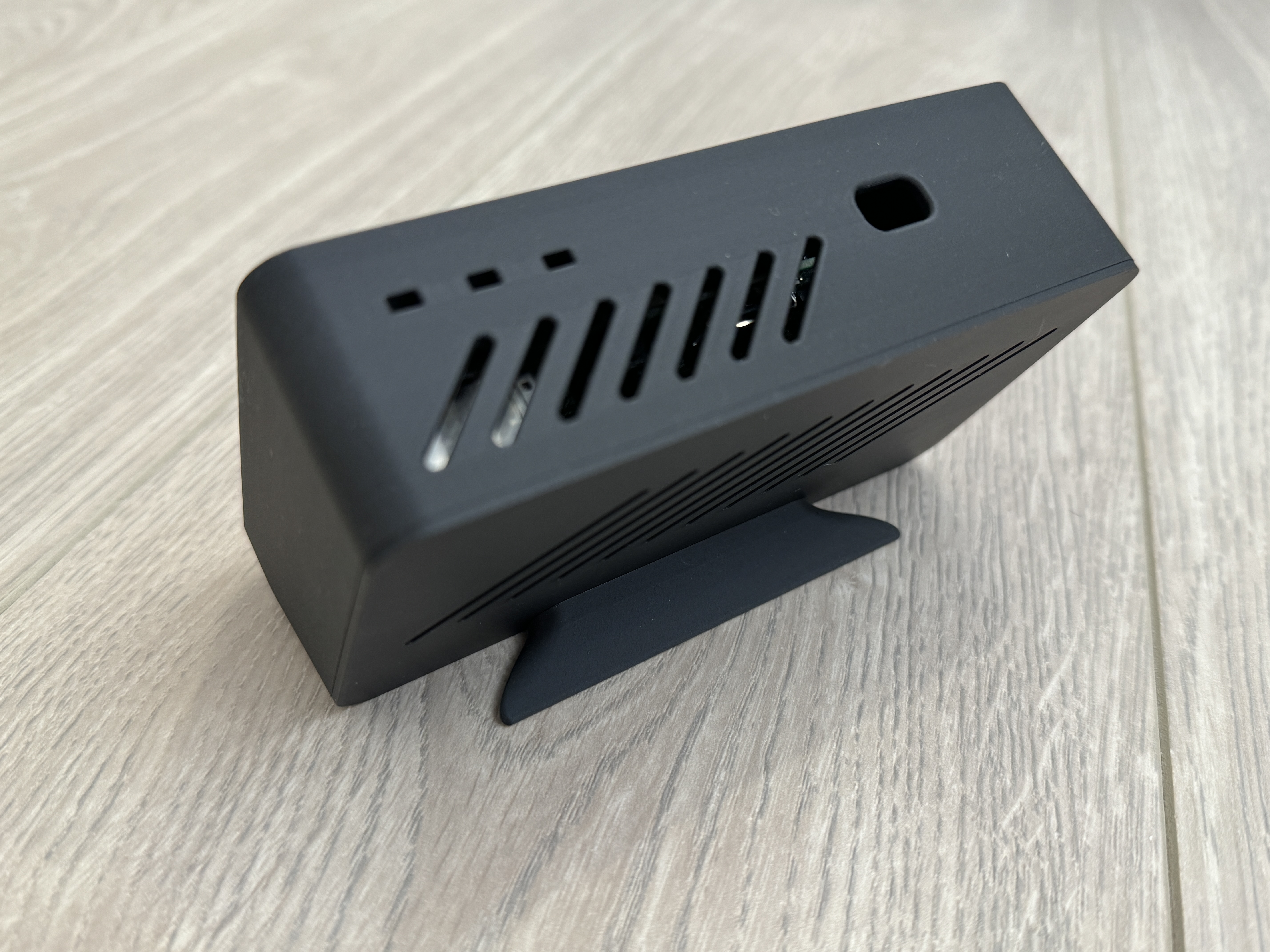

Raspberry Pi 3B+ with BTT TFT50 Screen Enclosure (Klipper screen, Home assistant)

Download, slice and print this model in the MakerSpell app — available on Android and Windows. Get the app
Model Overview & Print Notes
This is my take on a case for an RPI 3B+ attached to a BTT TFT50 v2.1 screen with ventilation and access to the screen buttons. Useful for a remote klipper screen install, Homeassistant dashboards or anything a little touchscreen computer can do! V2 released! Key changes: Use of a USB-C breakout board to allow cleaner wire routing and USB C PD power delivery M3x8 screw to hold the foot Introduction I wanted to create a remote klipper screen touch screen device to control my 3D printers that was not attached to the printers themselves to place on my work desk. However I could not find an enclosure that met all my requirements: Made for a RPI 3B+ and BTT PI TFT50 v2.1 touchscreen Slightly angled so I can use as a touch screen without knocking it over Passive ventilation - no fans needed Beautiful enough to place on my work desk Screwless - everything snap fits together So this design was born! Use cases While I have configured it to run klipper screen, this little stand alone computer can run the rPI desktop operating system and hence, can act as a touch tablet for any use - Homeassistant dashboards , a mini tablet or custom voice assistant . Basically anywhere you'd like a small computer with a touch screen! Print settings: Print with the below settings in your favourite slicer: 0.2 layer height 3 perimeters 15% infill No supports needed Outer perimeter first or “inner-outer-inner” mode in Orca slicer, for best dimensional accuracy Matte PLA / ABS GF/CF for a smooth look and finish This case has a tight and precise fit so make sure any shrinkage compensation is applied to your slicer. Bill of materials: RPI 3B+ Heatsink for the RPI chip (optional but recommended) BTT Pi TFT50 - the 2.1 version Some superglue to glue the foot to the rear panel Matte PLA recommended due to its looks but any material would do. For ABS/ASA make sure you set an appropriate shrink factor in your slicer else the case won't fit due to material shrinkage. V2 Bill of materials RPI 3B+ / Pi 4 Heatsink for the RPI chip (optional but recommended) BTT Pi TFT50 - the 2.1 version 1x M3x8 FHCS for the foot. USB Type-C Female Breakout Board (with resistors to allow PD delivery) Micro USB Male Type B 5-Pin Jack Port to power the rPI. Assembly: Firstly assemble the rear panel by gluing the foot to the bottom rear as below: Install the DSI cable to the screen and the RPI. Also install your SD card and operating system. You want to do this prior to installing it in the case as it will be fully enclosed with no access to the SD card once assembled. Install the screen in the case and push firmly to seat it against the mounting tabs. These are friction fit so some slight force may be required to firmly secure the display in its place Then proceed with mounting the RPI to the rear of the screen as below: Finally push the rear cover on and secure with the snap fit connectors Your mini computer is now fully assembled Last step is to plug it in from the cutout on the top of the case. Any small factor micro USB connector should work well for this with adequate clearance. V2 Assembly:
💬Baskı İncelemeleri & Yorumlar(0)
★4.9 / 5.0· Başarılı Baskı