


Download, slice and print this model in the MakerSpell app — available on Android and Windows. Get the app
Model Overview & Print Notes
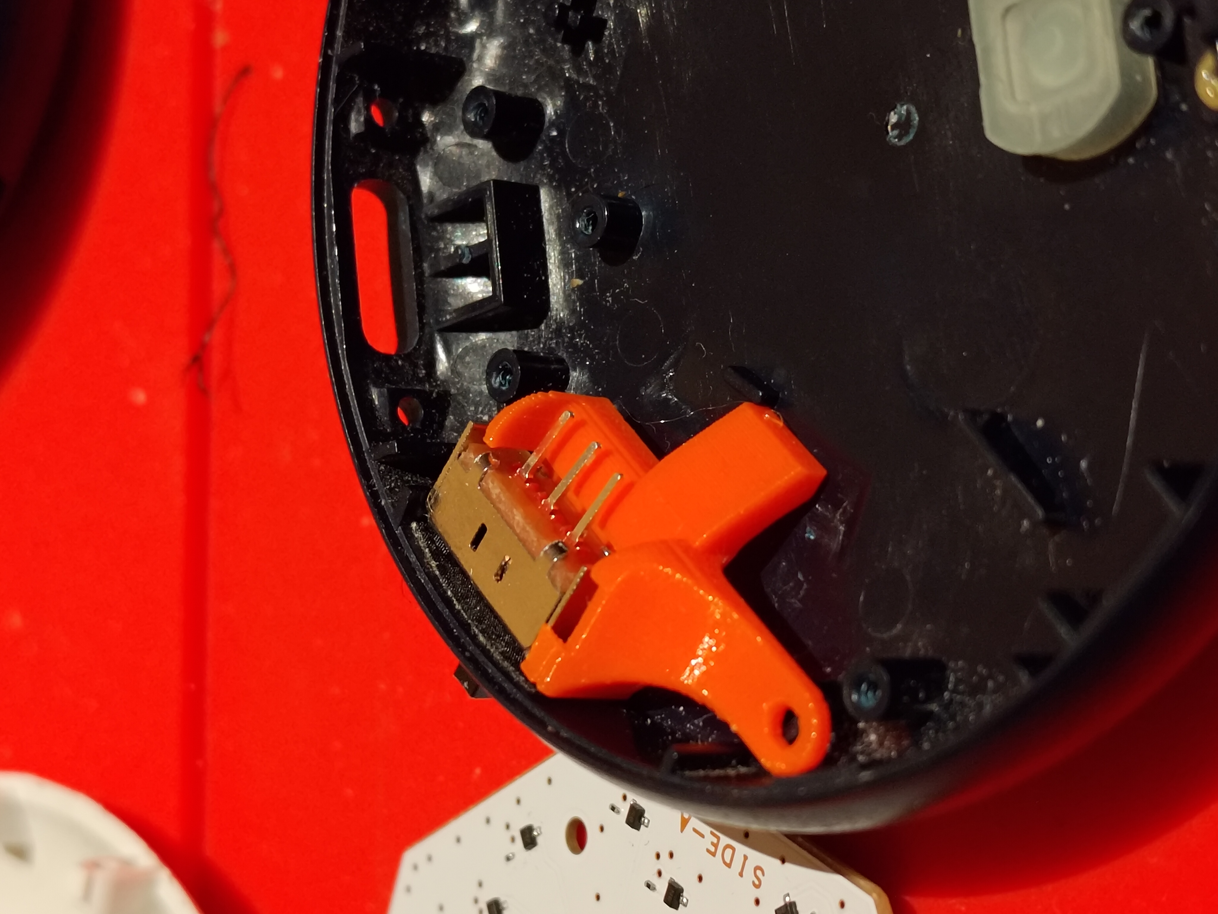
DISCLAIMERS: Modifications void warranty . Understand that modding is at your own risk. I am not liable for damage you may induce by accident This mod uses a specific switch. If you have other (generic) switches you want to use. Please contact me with dimensions, datasheet or model-nr and I'll make variants for them. this mod removes the speaker. So if you are attached to the pikachu noises. Consider an alternative where the speaker remains This mod can automate catching of pokemon to the extent that you barely have to do anything. It is practically cheating and as such it can spoil the fun for oneself. Another little Pokemon Go Plus+ switch jig. Rather than use a generic switch, this one is designed for a specific new switch I could be sure would be source-able from major distributors like Mouser and Digikey with a couple years worth of rated cycles. As such this may not be a good fit if you plan to use something like a generic bag of micro-switches from amazon. Switch specs are at bottom of description. The jig is a bit chaotic looking as I went for a barebones approach trying to keep space use to a minimum without compromising sturdiness. It does fit nicely though with a screw-mount matching that of the speaker whose place it occupies. It has been designed to keep the switch from moving around and most of the time does so with almost no wiggle. Requirements: Small soldering iron Small Philips screw-driver for the tiny screws Tweezers 2-3 thin wires and the ability to cut/strip them. I used wires stripped from a rainbow ribbon cable (same as typical jumper wires) Some solder Some Solder-Flux (to help with desoldering existing cables) A Same-Sky (formerly CUI) SLW-116641-5A-S-D switch Printing: Should work with any printer that is modestly accurate with dimensions. My MK4 was spot on. I recommend printing with PETG using a 0.4 or smaller nozzle The 3mf file has the model orientated with a few supports painted on for quickly getting going Pokemon Go Plus+ Disassembly Instructions: (I highly recommend watching a youtube video on this to help as visual guide, for posterity I will repeat the instructions here) Unscrew the two screws beside the USB-C port. These hold the top in place. Besides screws the top has double-sided tape sticking it to the battery. To open with as little risk as possible do the following: Pry open the top at a point just to the left of the USB port with a bit of plastic. This is the weakest point of the retention clips. Should not be difficult as I could do it with a finger nail Once you got an opening: slide in something to wedge it open. Plastic, guitar/repair pick, an old rewards card. So long as it keeps it open. Leave it like that for a while. The double-sided tape will slowly let loose. If feeling daring you can pry it open so you can wedge the plastic between the body and the screw-mount. Eventually you should be able to open it with little resistance. Be carefull around the opposite area to the right, which is where the ribbon cable lies. Once open. Start removing screws so you can remove the parts like the battery. I recommend disconnecting said battery. NOTE: The Battery connector is clicked into place from the top. Not inserted like most regular connectors. To disconnect you want to pry it off at where the cables enter the connector (without tugging the cables!). Ideally with a spudger or something like it. To reinstall you later simply click the connector back in place by pressing it in. Eventually you should just have the motherboard with the front PCB, the speaker and the Vibration motor. At this point you can bring out the soldering iron and perform the actual modifying. Modifying To make room for the switch you will need to remove the speaker. To do so I recommend putting some solder flux at where its soldered to the main board and melt the pad so you can pull out the wire with tweezers. You can store the speaker away should you wish to undo the mod later. Remove the black cable of the Vibration motor from its pad. Start preparing the switch for attaching to pads. You will want the center pin to have a cable that can reach the pad to which the vibration motor was connected. One of the other two pins will need a long cable that can reach the top-board with the leds. (optionally) you can give the left-over pin a cable reaching the Vibration motor cable. This would re-enable the vibration motor when the mod isn't engaged. Alternatively you can remove the motor altogether by de-solding its other cable On the top board there should be a tiny little pad to the right of where the ribbon is attached. This is a Test-pad for the switch and the ideal place to solder the cable from the switch to. (Optionally) You can try to dim the leds a bit if you want. I used paper I coloured black with markers that i stuck over the leds. In the main case there should be a small mesh covering the speaker hole. You will want to remove this so the switch can poke through. Re-assembly start with lowering in the mainboard with the vibration motor (if still using), switch in the jig and USB. Try to route the cables from the switch so it sits snug underneath or is routed around the mainboard. Take care that the cable to the top board isn't too tight or pressing against either the ribbon cable or antenna cable. In order screw in place first the Mainboard, then the USB board and finally the switch jig. I'd recommend tightening it while pressing the jig against the side to reduce any remaining wiggle. Screw the top PCB back unto to the top and check if it can easilly be fitted back unto the main case. Once the PCBs are screwed back in place. re-attach the battery and give it a quick test while still open if everything is working. If so. Screw the battery in-place, close the Plus+, screw in the last two screws next to the USB ports and you are done!! HOW IT WORKS: The trick behind the mod is that whenever the Plus+ detects something like a Pokemon or a Stop. It will spin the vibration motor. It does so by turning on a small load switch that connects the motor to the GND. Meanwhile the button is so that whenever you press it: it pulls a signal to GND. So if you connect the button output to the same little load switch the Vibration motor uses. You can make it look like the button is pressed whenever it normally spins. Thus you get that the Plus+ presses its own button. Ensuring that will throw at EVERY pokemon in rapid succession with your ball of choice and spin every stop. While at the same time shushing the motor. The downside is that while the mod works fairly reliable for pokemon and stops. It does start to interfere with the Sleep tracking function. There are other ways to modify without a switch so that it ONLY responds to pokemon and ignores stops/sleep. But that is beyond this project. Switch Specs: The switch used is a: Same Sky SLW-116641-5A-S-D A simple small switch that costs about 50 cents at most distributors with 10000 cycles rating. It is designed mostly for being mounted on PCBs underneath control panels. Dimensions are: Main body (LxWxD): 11.6 x 4.1 x 6 mm Switch: 5 x 2 x 2 mm. With 2.5mm travel Pins are spaced at 2.5mm
💬Baskı İncelemeleri & Yorumlar(0)
★4.9 / 5.0· Başarılı Baskı