
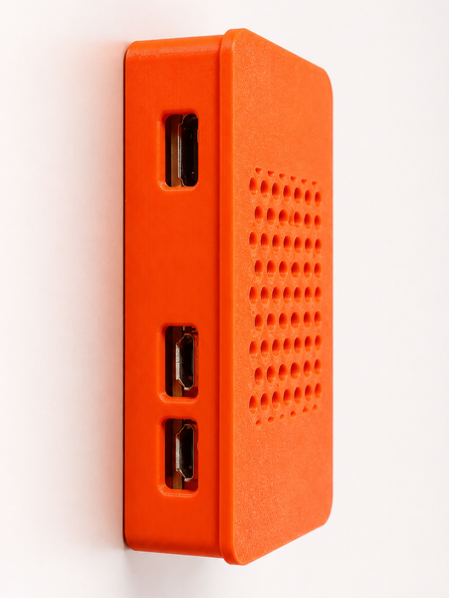

Parametric Electronics Enclosure / Case Generator

Download, slice and print this model in the MakerSpell app — available on Android and Windows. Get the app
Model Overview & Print Notes
Create a custom-fit enclosure for almost any small electronics project directly in MakerWorld’s Parametric Model Maker or OpenSCAD. Enter the dimensions of your PCB, choose the lid style, position the required connector openings, and generate a ready-to-print project box sized specifically for your hardware. The model supports Raspberry Pi boards, ESP32 projects, Arduino-compatible boards, sensor modules, custom PCBs, battery-powered devices, and many other electronics projects. Unlike a fixed enclosure, this generator lets you adjust the case around your board instead of designing your project around an existing box. Main Features Enclosure dimensions generated from PCB measurements Adjustable clearance around and above the board Separate printable base and lid Screw-fastened, snap-fit, or friction-fit lid options Up to eight independently configurable connector openings Openings can be placed on any side of the enclosure Adjustable port width, height, position, and corner radius Four configurable PCB mounting posts Adjustable mounting-hole spacing and pattern offset Slotted or honeycomb lid ventilation Optional embossed or recessed lid label Optional wall-mounting tabs Rounded enclosure corners Adjustable wall, floor, and lid thickness PCB and component-volume preview for checking fit Print-plate layout for producing the base and lid together Small tolerance test part for checking lid fit before printing the complete case Supported Projects The generator can be used for projects such as: Raspberry Pi Zero and similar single-board computers ESP32, ESP8266, and RP2040 projects Arduino and compatible development boards Custom PCBs Sensor and monitoring devices Home automation controllers LED controllers Battery-powered electronics USB adapters and interface boards Small power supplies Prototype electronics Wall-mounted control modules Configuring the Enclosure Begin by entering the dimensions of your PCB: PCB length PCB width PCB thickness Maximum component height If the board includes mounting holes, enable the PCB posts and enter the mounting-hole spacing. The complete mounting pattern can also be shifted to support boards whose holes are not centred. Connector openings are configured individually. Each opening has controls for: Enabled or disabled Enclosure side Horizontal position Vertical position Width Height Corner radius This allows the enclosure generator to support USB, HDMI, power, Ethernet, switches, buttons, displays, ribbon cables, SD cards, and other connectors. Lid Options Friction-Fit Lid The lid is held in place by a fitted internal skirt. This is a good choice for enclosures that need occasional access and do not require tools. Snap-Fit Lid Flexible clips retain the lid without screws. This is useful for compact consumer-style enclosures, although fit may depend on material choice and printer calibration. Screw-Fastened Lid The lid is secured using screws positioned near the enclosure corners. This is the most secure option for permanent installations, wall-mounted projects, and enclosures that may be handled frequently. Ventilation The lid can be produced with: No ventilation Parallel ventilation slots Honeycomb ventilation Vent dimensions and density can be adjusted to suit the amount of airflow required. Ventilation is recommended for processors, voltage regulators, power supplies, LED controllers, and other components that generate heat. Labels An optional label can be added to the lid as either: Raised text Recessed text This can be used for project names, device identifiers, voltage labels, room names, network roles, or assembly markings. Wall Mounting Optional mounting tabs can be added to the enclosure for installation on a wall, panel, cabinet, workbench, or other flat surface. The tab dimensions and mounting-hole diameter can be adjusted for the fasteners being used. Recommended Workflow Measure the PCB and its tallest components. Enter the PCB dimensions and clearances. Configure the mounting-hole pattern. Add openings for every required connector. Render the assembled preview. Confirm that the PCB and component preview do not intersect the case. Print the tolerance test. Adjust the lid clearance if required. Generate and print the base and lid. Always measure the actual board and cables when possible. Manufacturer drawings describe the PCB and connector locations, but some cable plugs have oversized moulded housings that require additional clearance. Printing Recommendations Suggested starting settings: Layer height: 0.20 mm Walls: 3 or more Top and bottom layers: 4 or more Infill: 15–25% Supports: normally not required Base orientation: open side facing upward Lid orientation: outside surface on the build plate PLA is suitable for most indoor electronics projects. PETG is recommended for warmer environments, wall-mounted installations, and parts that require more durable snap features. For PETG or printers with tighter tolerances, slightly increase the lid-fit clearance before printing the full enclosure. Screw and Post Notes The PCB mounting-post holes are intended as printable pilot holes. Final screw fit depends on the printer, material, extrusion width, and type of screw being used. For critical assemblies, print a small test or drill the holes to the required finished diameter. Do not overtighten screws against a PCB. Nylon washers or small printed spacers may be useful for boards with exposed traces near the mounting holes. Important Limitations This generator uses rectangular, rounded connector openings on the enclosure walls. It does not currently generate: Arbitrary SVG-shaped wall cutouts Lid-mounted rectangular connector cutouts Automatic connector detection from PCB files Waterproof seals Integrated hinges Cable glands DIN-rail clips These features may be added in future versions. MakerWorld Parametric Model Maker The model is organized with simple exposed controls intended to work well in MakerWorld’s Parametric Model Maker. All connector file paths and complex data structures have been avoided so that the model can be customized without editing the source code. For advanced customization, the OpenSCAD source can also be downloaded and modified locally. Share Your Presets This generator can produce a large range of project-specific enclosures. Consider sharing your successful settings and print profiles for popular boards so other makers can quickly generate compatible cases. Please include the exact board revision when sharing a preset, as connector and mounting-hole positions can differ between versions.
💬Baskı İncelemeleri & Yorumlar(0)
★4.9 / 5.0· Başarılı Baskı